DirectX 11 and WinUI 3.0
Loading a Model
June 13th, 2023
Let's continue with our look at how to render stuff with DirectX 11 inside a WinUI 3.0 window. Now that we have rendered a triangle successfully, we know the pipeline works, which isn't a small feat. Eventually, I'm going to move more towards doing 2D stuff, like painting with Direct2D1. But since we started with Direct3D, let's at least load a 3D model in the app. For that, we need something to open the file with.
Assimp (Open Asset Import Library) is a cross-platform library used for importing and processing 3D model files. It provides a simple interface to load various 3D model formats (like FBX and OBJ) and access their data, such as vertices, textures, materials, and animations, making it easier to work with 3D models in different applications. And most importantly, it's free! You'll find Assimp on NuGet.
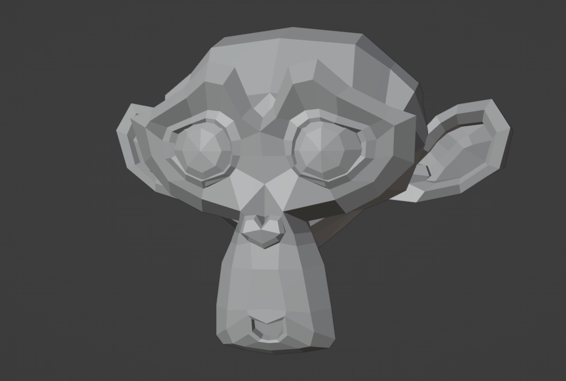
Of course, we also need a 3D model. You can use anything you'd like, but I'm going to export an FBX of Blender's default monkey, Suzanne. You can download the file from the link, if you don't feel like working with anything else. Just place the FBX file at the root of your project and make sure it's included in your compile.
monkey.zip (27 KB)
To get the model imported into our app, we declare a variable called "importer" of type AssimpContext. This variable will be used to interact with the Assimp library.
private AssimpContext importer;

public void CreateResources()
{
	importer = new AssimpContext();
	string modelFile = Path.Combine(AppContext.BaseDirectory, "Monkey.fbx");
	Scene model = importer.ImportFile(modelFile, PostProcessPreset.TargetRealTimeMaximumQuality);
	...
}
We then initialize the "importer" which sets up the environment to work with 3D models. Next, we specify the file path of the 3D model and use the "importer" to load the model file and store the result in a variable called "model". The "importer.ImportFile" method processes the model file, applying any necessary optimizations or adjustments based on the specified PostProcessPreset.
The Vertex and Index Buffers
Defining vertices and indices by hand was fine for a single triangle, but now we are handling complex 3D meshes, so there needs to be a better way. And there is! Let's first create a struct to lay out the data structure of our vertices.
[StructLayout(LayoutKind.Sequential)]
public struct Vertex
{
	public Vector3 Position;
}
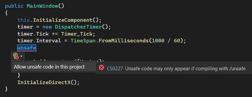
There's only one field so far, but as we start to add more fields (such as normals) in the future, a data structure like this becomes essential. And since the struct has all the members a vertex is going to hold, we can calculate the size of the stride (single element in vertex buffer) by taking the size of the Vertex. However, since Vertex doesn't have a predetermined size, we have to use unsafe code to get the size.
private int stride;
private int offset;

public MainWindow()
{
	...
	unsafe
	{
		stride = sizeof(Vertex);
		offset = 0;
	}
}
By default, C# enforces a safe programming environment, where the runtime handles memory management and ensures type safety. However, in certain scenarios, such as when working with interop code or optimizing performance-critical operations, the unsafe keyword can be used to bypass these safety checks and gain more control over memory manipulation. Using unsafe code can be potentially dangerous, as it can lead to memory corruption, security vulnerabilities, or undefined behavior if not used correctly. Therefore, it should be used with caution and only when necessary.
In theory, there should be a way to do everything without resulting to unsafe code. However, there may be certain scenarios where working with Direct3D involves low-level memory operations or interop with unmanaged code, which might require the use of unsafe code. For example, when working with certain Direct3D features or when optimizing performance-critical sections of code, you may need to use unsafe code to directly access memory or perform pointer-based operations. If you don't, the performance could suffer drastically depending on the situation.
In this guide, we just bite the bullet and use unsafe when necessary. You can either set "Allow unsafe code" option in the project settings, or by enabling it with the quick actions.
Since we're removing the old vertices array, let's create a new global Vertex list for them instead.
private List<Vertex> vertices;

public void CreateResources()
{
	...
	Mesh mesh = model.Meshes[0]; // Assuming the model has at least one mesh
	vertices = new List<Vertex>();

	for (int i = 0; i < mesh.Vertices.Count; i++)
	{
		Vector3D vertex = mesh.Vertices[i];

		Vertex newVertex;
		newVertex.Position = new Vector3(vertex.X, vertex.Z, -vertex.Y);

		vertices.Add(newVertex);
	}
	...
}
Here, we extract vertex data from the mesh and store it in our vertices list. Storing the vertex data allows us to access and manipulate the individual vertices of the mesh later on during the rendering process. Each vertex here only contains its position in 3D space. By collecting and organizing the vertex data in a list, we can efficiently iterate over the vertices when rendering the model. Later on, this allows us to perform operations like transformations, lighting calculations, and texture mapping on each vertex.
It's noteworthy, that we're changing the order of the coordinates (vertex.X, vertex.Z, -vertex.Y) as we save the vertices in the list. This leads us to a... super interesting topic of 3D coordinate systems.
Here's a little exercise for you: hold out your right hand and make a thumbs-up sign. Your fingers are making a half-circle, right? Now, extend your index finger straight and bend your middle finger so it points towards you. Your thumb represents the X-axis, your index finger is the Y-axis, and your middle finger is the Z-axis. In a right-handed system, positive X points to the right, positive Y points up, and positive Z points forwards (out of the screen). However, if you do the same thing with your left hand and hold it in a way that the index finger is pointing the same direction as it was with you right hand, well now the middle finger (Z-axis) is pointing towards the screen, not away from it.
Example. Let's say you have a 3D model that was created in a system where the Y-axis is up (or "Y-Up"), and the Z-axis is forward. This is common in a lot of 3D modelling software. However, you might be using a graphics system like DirectX where the Y-axis is forward and the Z-axis is up (or "Z-Up"). So, if you try to render a model created in a Y-Up system directly in a Z-Up system, things can get a bit... topsy-turvy. Your model might appear to be lying on its side! It's like trying to fit a square peg into a round hole, it just won't look right.
This is where the magic of new Vector3(vertex.X, vertex.Z, -vertex.Y) comes in. It transforms the square peg into a round one. Here's what each part does:
- vertex.X: This stays the same in both systems, no changes needed.
- vertex.Z: Here's where things get interesting. We're using the Z value from the Y-Up system as the Y value in the Z-Up system.
-vertex.Y: Even more exciting! We're using the negative of the Y value from the Y-Up system as the Z value in the Z-Up system. Why the negative? Well, it's related to the direction of the axis, which is flipped between the two systems.
The model of Suzanne was exported with the defaul -Z Forward and Y Up transfroms from Blender. This transformation just makes sure that the model looks the same way in our application as it did in Blender. If you use some other model exported with different settings, you're going to have to figure out which value to use with which axis.
After the vertices are transformed and saved into the list, it is time to switch them to an array, because the BufferDescription and DataStream expect an array.
Vertex[] vertexArray = vertices.ToArray();
BufferDescription vertexBufferDesc = new BufferDescription()
{
	Usage = ResourceUsage.Default,
	ByteWidth = sizeof(float) * 3 * vertexArray.Length,
	BindFlags = BindFlags.VertexBuffer,
	CPUAccessFlags = CpuAccessFlags.None
};
using DataStream dsVertex = DataStream.Create(vertexArray, true, true);
vertexBuffer = device.CreateBuffer(vertexBufferDesc, dsVertex);
We are only changing the DataStream to use vertexArray and the ByteWidth to be calculated with the vertexArray.Length. Otherwise, it's the same buffer creation section from before.
With the index buffer, we do a similar trick.
private List<uint> indices;

public void CreateResources()
{
	...
	indices = new List<uint>();
	foreach (Face face in mesh.Faces)
	{
		indices.AddRange(face.Indices.Select(index => (uint)index));
	}

	uint[] indicesArray = indices.ToArray();
	BufferDescription indexBufferDesc = new BufferDescription
	{
		Usage = ResourceUsage.Default,
		ByteWidth = sizeof(uint) * indicesArray.Length,
		BindFlags = BindFlags.IndexBuffer,
		CPUAccessFlags = CpuAccessFlags.None,
	};
	using DataStream dsIndex = DataStream.Create(indicesArray, true, true);
	indexBuffer = device.CreateBuffer(indexBufferDesc, dsIndex);
	...
}
Here, we're taking the faces of the mesh and adding all the indices from all of them into the indices list. Then we convert the list to an array and use it to create the BufferDescription and the Buffer.
At this point, it would also make sense to update the Draw call to reflect the real number of indices we want it to draw.
deviceContext.DrawIndexed(indices.Count, 0, 0);Even at this stage, if you run the application, it will render the 3d model. It does a poor job, but it does render it. We can do better.
Visual Studio project:
d3dwinui3pt6.zip (48 KB)
D3DWinUI3 part 6 in GitHub


